简单的光开关电路,Simple optical switch

Introduction
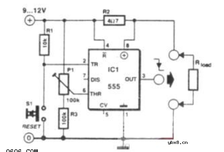
The 555 is proved to be the most versatile and ubiquitous IC all over the world.This is a possible use: simple inverting schmitt trigger.
Circuit explanation
When the phototransistor is stroken by IR light it conducts and the voltage between the 1Mohm resistor(arbitrary) and the phototrans drops from VCC to lower values. When the voltage drops lower than VCC/3 the 555 is triggered and goes high (from 0 TO VCC). The amount of light that strike the phototrans necessary to bring his collector to VCC/3 is determined by the resistor (Vdrop = Icollector * R , so , if Vdrop= 2*VCC/3, the resistance needed to set the threshold on current is R=2*VCC/(Icollector*3)). High sensibility phototrans would need a smaller resistor, and weaker phototransistors higher value resistor, you can also use a trimmer to set the on threshold level with precision. The time of phototransistor isn't critical. The 555 has high current capability and can drive various devices, such as Bipolars, relays, bipolars+relays, mosfets, mosfets + totem pole , or give a logic output (see pic).
In case you need to trigger something when the gate is blocked (for example a burglar alarm, or a multistage coilgun) you need to invert the output, which is accomplished using a small bipolar transistor wired in an inverting setup (see pic) or swapping the positions of phototransistor with the resistor, so the voltage will drop under VCC/3 when blocked: The formula to determine the resistance to turn off at Icollector is R=VCC/(Icollector*3).
相关热词:#开关电路
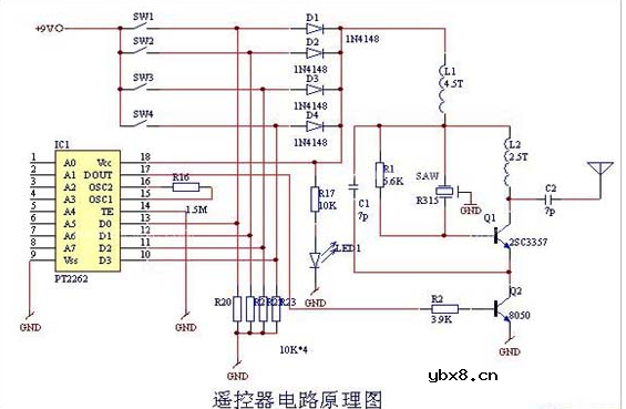
 无线遥控器电路图制作
时间:2026-03-07
 无线电遥控门铃电路原理图
时间:2026-03-07
 NE555过流保护检测器电路图
时间:2026-03-07
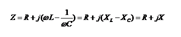 串联谐振升压原理
时间:2026-03-07
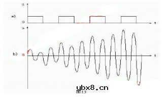 谐振回路的工作原理
时间:2026-03-07
 电容降压电路原理
时间:2026-03-07
 实用的电容降压电路
时间:2026-03-07
 低成本的阻容降压电路原理图分析
时间:2026-03-07
 阻容降压原理及电路
时间:2026-03-07
 阻容降压电路的误区
时间:2026-03-07
 彩灯电路
彩灯电路
时间:2026-03-05
三相异步电动机原理
时间:2026-03-04
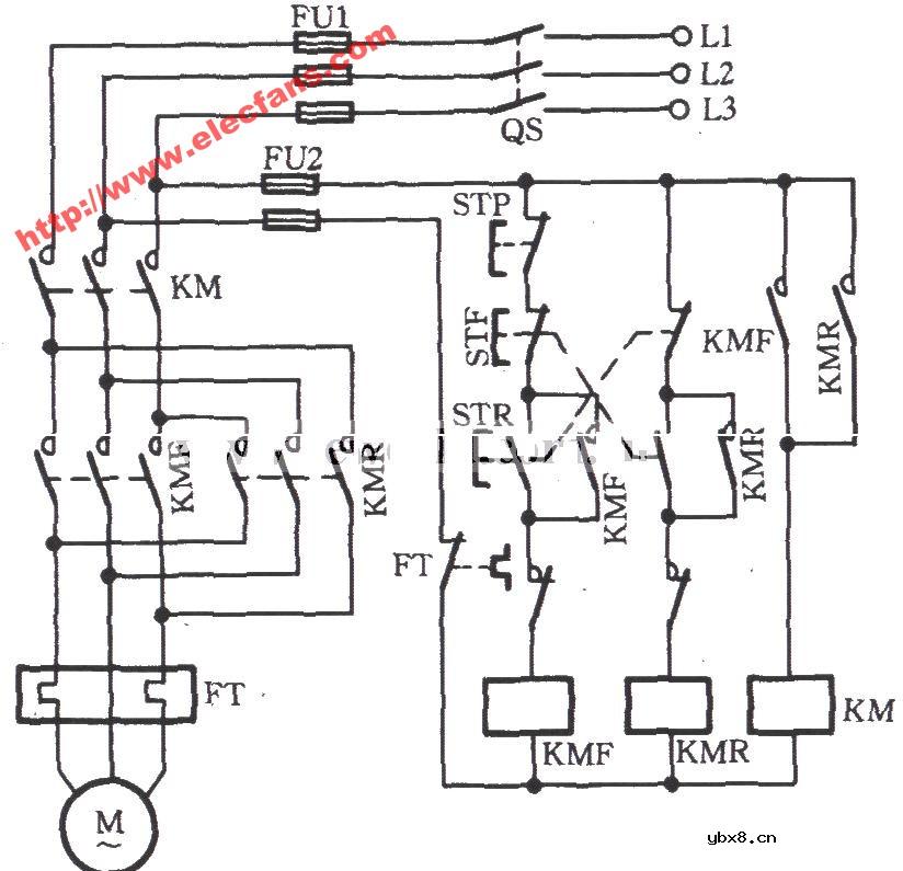 电动机单线远程正反转控制电路图
时间:2026-03-04
三相异步电动机的七种调速方式
时间:2026-03-04
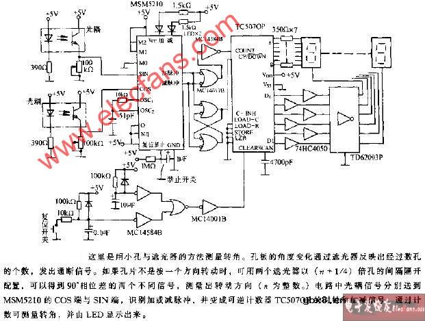 转角测量电路
时间:2026-03-05
 经典的正弦波发生电路
时间:2026-03-05
三相异步电动机的拆装详讲
时间:2026-03-04
 USB转232电路图
时间:2026-03-04
电度表的工作原理
时间:2026-03-04
 电风扇红外遥控器2
时间:2026-03-04