红外数字温控风扇电路,IR Digital Thermostat for FAN
Introduction
--------------------------------------------------------------------------------
This circuit measures temperature in Celsius scale and displays it on an alphanumeric LCD screen
When temperature rise to 40 C an alarm is activated and at the same time a relay is also activated which
drives a fan to keep the temperature at a level.
Another feature of this circuit is that you can use the keys "1,2,3,4" of a Philips TV IR remote to turn on or off three relays, The key '4' is used to turn on or off the over temperature alarm.
Hardware
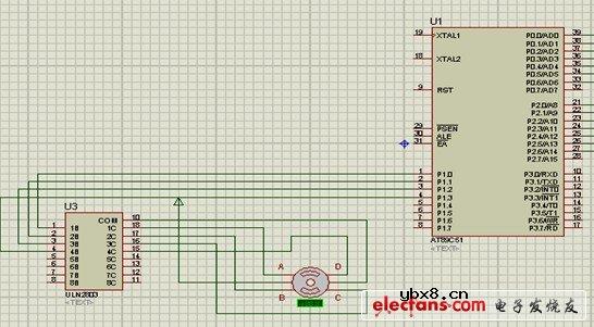
The brain of this circuit is AT89C51 microcontroller. LM35 is a 3 pin chip which is easily available in TO-92
package. LM35 can sense temperature from 0 C to 100 C but it gives analogue output the microcontroller does not understand analogue data, so ADC0804 (analogue to digital converter) is used to convert it to digital form.
This digital data is given to port 1 of microcontroller. (See the circuit diagram) this data is processed by microcontroller and temperature is displayed on lcd connected to port 2.The control pins of lcd are connected to port 0. port 0 also controls the relays and alarm.

The ULN2003 chip is used to drive the relays because the microcontroller pins don't have enough current to drive them. so relays cant be connected to microcontroller pins directly further more the relays are inductive load and reverse current is generated in them. Pin 1 to 7 are the inputs and 10to 16 are respective outputs. Pin 8 is ground and pin 9 is connected to the output of 7808 voltage regulator.
The 7805 voltage regulator drives rest of the circuit. I used a standard buzzer driven by LM555 timer/Oscillator chip. The chip is wired as a monostable multivibrator and at its output (i.e. pin no 3) a buzzer is connected.
Use any IR module and connect its Data out to pin 10 of microcontroller. The Relay connected to pin 13 of ULN2003 turns on when temp rises above 40 C so connect the fan to this relay.
Hardware
--------------------------------------------------------------------------------
As this circuit has many components I advice don't use Vero boards or point to point boards.
Use a standard pcb. A pcb file is included in the zip file it opens with a software called EAGLE You can download the demo version here its quiet simple and easy to use. So print the pcb on a glossy paper. now place the glossy paper on the pcb. The print should be on the copper side now use an iron to transfer the print on the pcb. After you are done dip the pcb in any enchant I used FeCl3 (ferric chloride). When your pcb is ready pour lots of water to remove any FeCl3 and remove the print using steel wool. Now drill holes and place components.
download the zip folder it contains the images of completed
project, hex file circuit diagram and pcb file.
click here for pcb, Circuit diagram and hex file in a zip
Click the picture below for a Larger View.

相关热词:#红外
 锐迪科PHS手机射频前端设计电路图
时间:2026-03-07
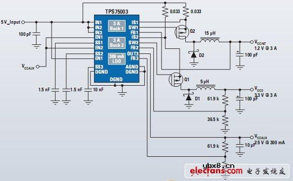 TPS75003芯片:为Spartan和Cyclone提供的电...
时间:2026-03-07
基于AT89C51的频率计硬件电路图
时间:2026-03-07
 步进电机驱动电路原理图
时间:2026-03-07
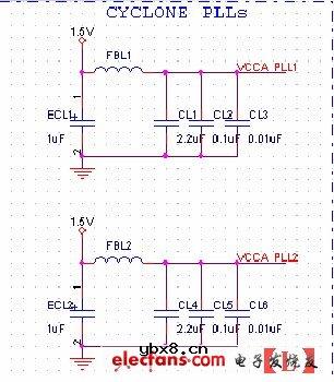 Altera PLL电源管脚滤波电路图
时间:2026-03-07
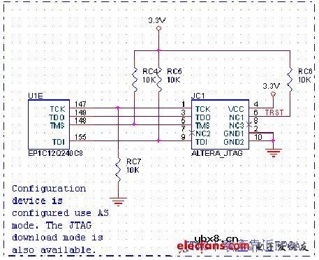 Altera JTAG下载和调试接口电路图
时间:2026-03-07
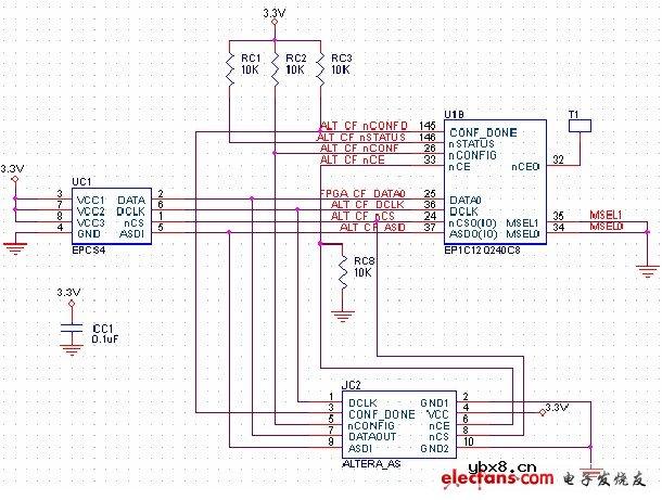 AS下载和调试接口电路(Altera FPGA开发板)
时间:2026-03-07
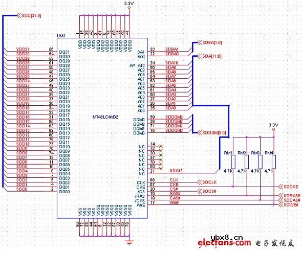 高速SDRAM存储器接口电路设计(Altera FPGA...
时间:2026-03-07
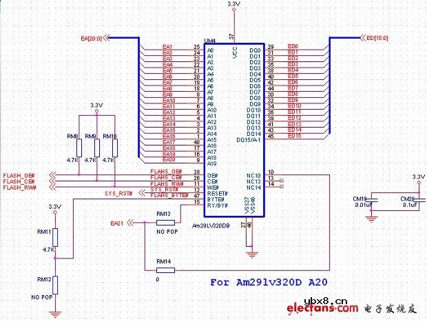 FLASH存储器接口电路图(Altera FPGA开发板...
时间:2026-03-07
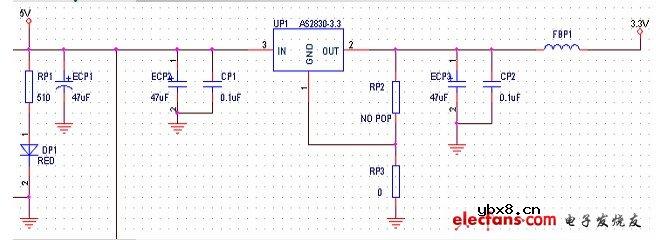 电源、时钟和复位电路图(Altera FPGA开发板...
时间:2026-03-07
 彩灯电路
彩灯电路
时间:2026-03-05
三相异步电动机原理
时间:2026-03-04
三相异步电动机的七种调速方式
时间:2026-03-04
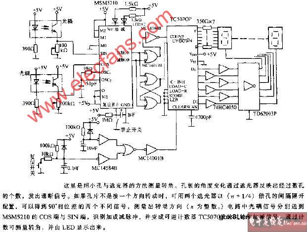 转角测量电路
时间:2026-03-05
 经典的正弦波发生电路
时间:2026-03-05
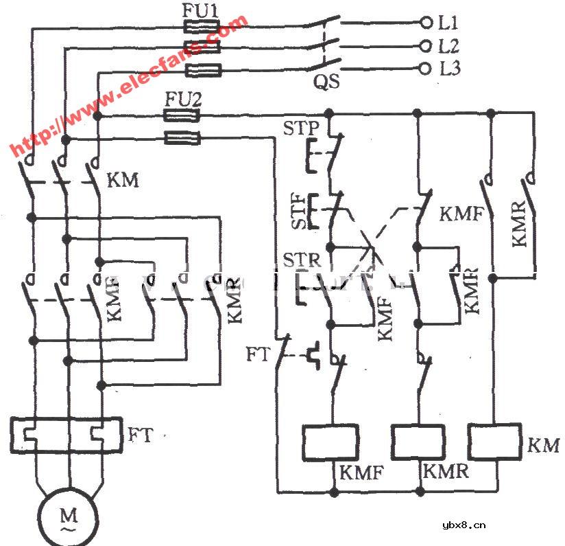 电动机单线远程正反转控制电路图
时间:2026-03-04
 USB转232电路图
时间:2026-03-04
电度表的工作原理
时间:2026-03-04
 电风扇红外遥控器2
时间:2026-03-04
三相异步电动机的拆装详讲
时间:2026-03-04