红外门电路2例 (Infrared gate 2)
This is an infrared gate with two sensors planned to use in the wall in the way behind a door. It can be applied in a toilet to keep track of that someone is inside exceeding a certain amount of time. After that time elapsed, the circuit triggers the digital output wich can turn on a ventillator. The time period the output is turned on can be separately controlled by a second timer.
If you plan to build this circuit, beware that you may have lots of difficulties though the schematic may seem simple. The construction of the circit requires some amount of equipment like an oscilloscope and a DVM, too. Without them, the device will do weird things you wouldn't expect, and even if it is correctly put together, you must adjust it with care both mechanically in its final place and electronically with the help of an oscilloscope. Only if you want to span about less than 20-30 inches with the infra diodes can forget about this calibration. Alternatively you can take ideas from this construction.
")
Schematics
The device consists of several parts, the most critical one is the panel with the infra LEDs. I tried to use several receiver transistors, but best result was given by infra receiver diodes used in TV remote control receivers. The receiver diodes must be properly shielded from the transmitter LED(s) otherwise the infra light will surely drive the receiver with a large enough signal. These photodiodes should only see infrared light coming from the mirror. The two very sensitive receiver parts should also be isolated from the transmitter electrically or the TX signal will get across the wires to the RX lines, which results the same effect as weak optical shielding. Use metal shielding around the receiver amplifiers where possible. The infrared transmitter LEDs should be close in wavelength to the max. sensitivity band of the receivers. You can experiment with using more LEDs and more current testing several resistor values, but don't exceed the 500 mA current limit flowing on the diodes or they will burn out. Do not shield the transmitters, allow the maximum amount of infralight to reach the mirror to extend the possible range.
")
") To start testing the infra LED panel, you wil need the infragate amplifier panel and the small transmiter driver. The TX driver will generate the digital signal for the LED driver on the LED panel. The digital signal is 1:10 on/off to achive good pe
To start testing the infra LED panel, you wil need the infragate amplifier panel and the small transmiter driver. The TX driver will generate the digital signal for the LED driver on the LED panel. The digital signal is 1:10 on/off to achive good pe
")
It is also important to protect the receiver diodes from direct light as natural light will weaken the sensitivity of the diodes, and lamps will transform the 50/60 Hz modulation present in the line power. Small noise is not problem, but the received signal from the TX generator should be stronger to be able to detect it. After the ST adjustments, connect LEDs to the 74123's TTL outputs through proper value resistors. The 74123 here is used as a demodulator. If there is a periodic signal change on the input, the output will be high, while if there is no activity on the input for a given period of time, the output falls low. When you cover the line of sight of one receiver diode, the corresponding LED turns off. There should not be any flickering in the turning on/off, the output should immediately respond to the change without blinking.
")
If still everything is correctly working at this point, the remaining digital circuit is the easy part of the work. The outputs of the previous circuit (LEFT, RIGHT) directly connect to the remaining part. The RS memory built from two NAND gates remembers the way of the last movement direction, so if someone is in or not. If you experience problems, connect another LED to pin 10 of the RS and check if this part does what it should. If there was any activity in the past minutes, the first timer is running, but it can only trigger the second timer part, if someone is still inside. The diode from the second timer output prevents resetting itself before the timing period is over in case of another movement. For a 1 minute timing (first timer) R=470k C=100u can be used, the second part would use R=1.5M C=470u for about a 15 minute timing (t=1.1RC). The output of the second timer (pin 9) can drive a relay activating the ventillator.
相关热词:#红外
 驱动信号发生器电路图
时间:2026-03-07
物理电路图分析方法
时间:2026-03-07
 利用“去表法”物理电路图的等效电路图转换
时间:2026-03-07
 电铃电路图解题思路分析
时间:2026-03-07
 并联电阻电功率的解题思路
时间:2026-03-07
初中物理的学习方法指导
时间:2026-03-07
 灯泡并联电路及接线图
时间:2026-03-07
 并联电路实物连接图
时间:2026-03-07
 并联电阻电路分析
时间:2026-03-07
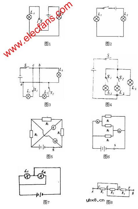 串并联电路的标准画法
时间:2026-03-07
 彩灯电路
彩灯电路
时间:2026-03-05
三相异步电动机原理
时间:2026-03-04
三相异步电动机的七种调速方式
时间:2026-03-04
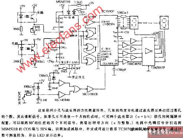 转角测量电路
时间:2026-03-05
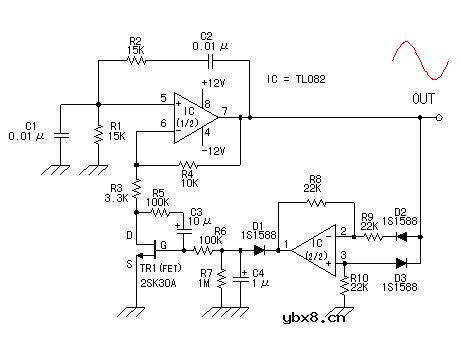 经典的正弦波发生电路
时间:2026-03-05
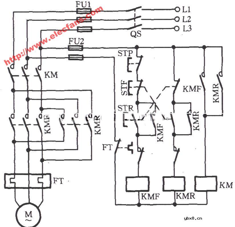 电动机单线远程正反转控制电路图
时间:2026-03-04
电度表的工作原理
时间:2026-03-04
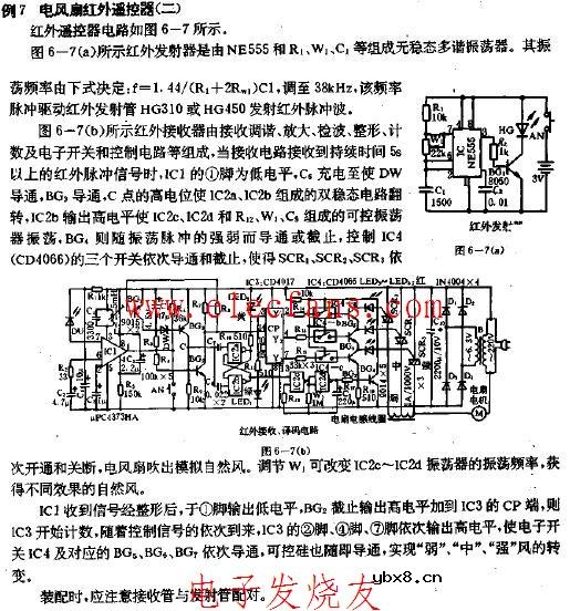 电风扇红外遥控器2
时间:2026-03-04
三相异步电动机的拆装详讲
时间:2026-03-04
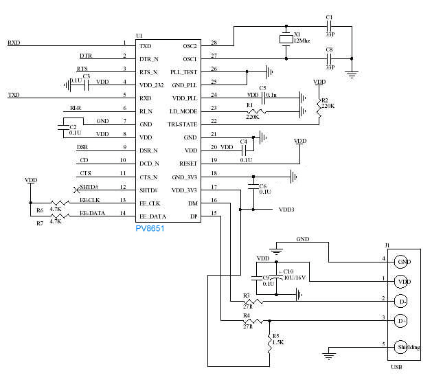 USB转232电路图
时间:2026-03-04